Bird Wing Automaton
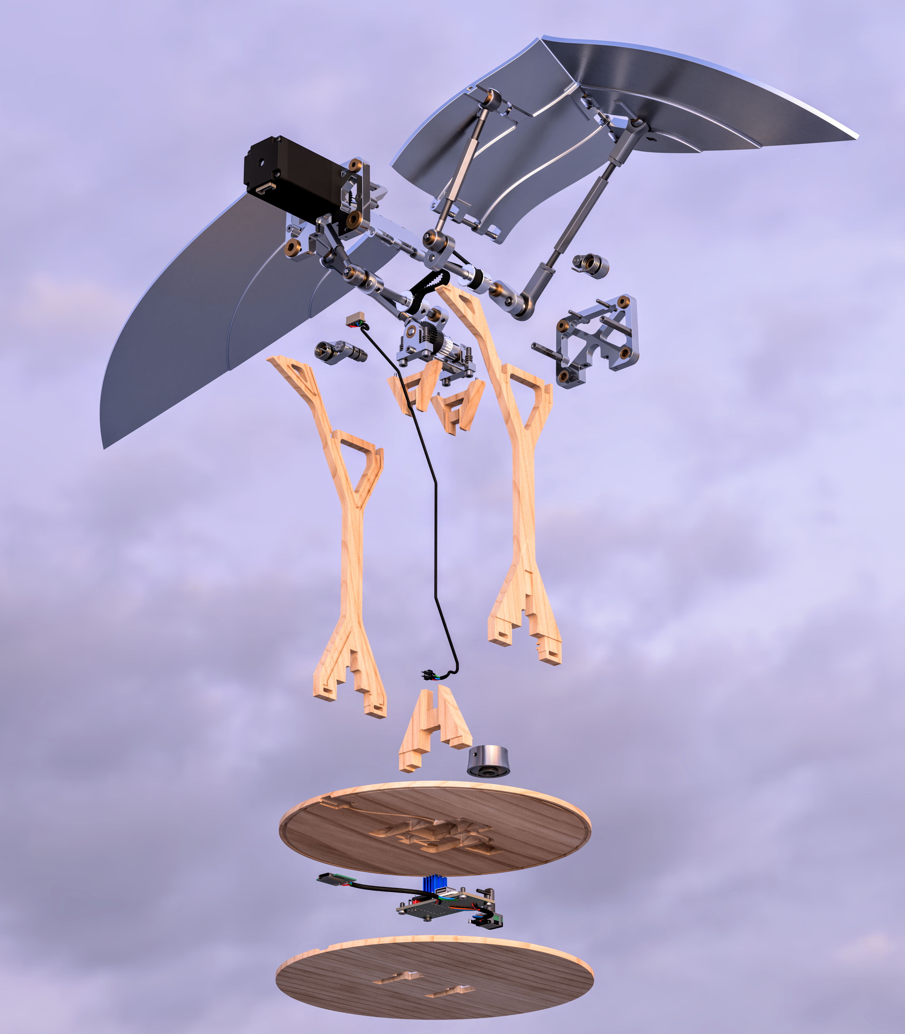
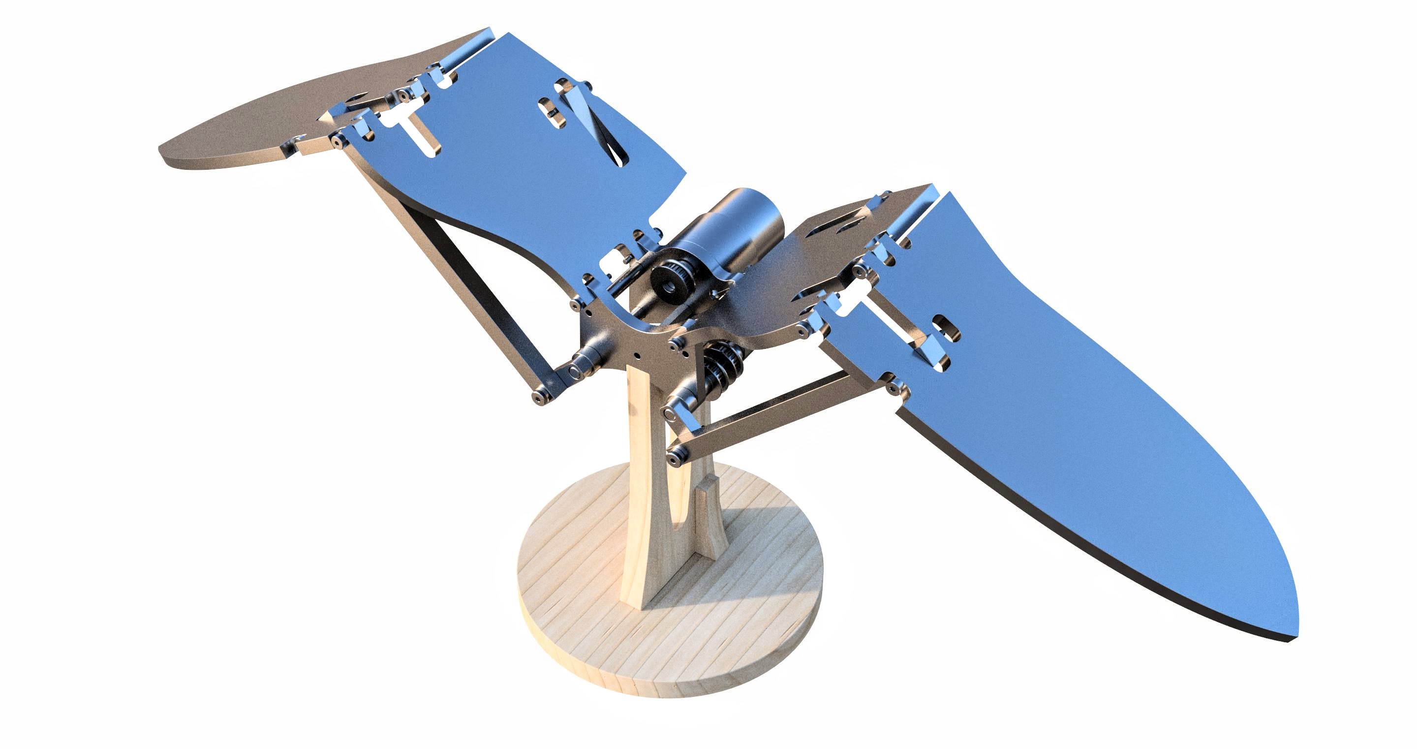
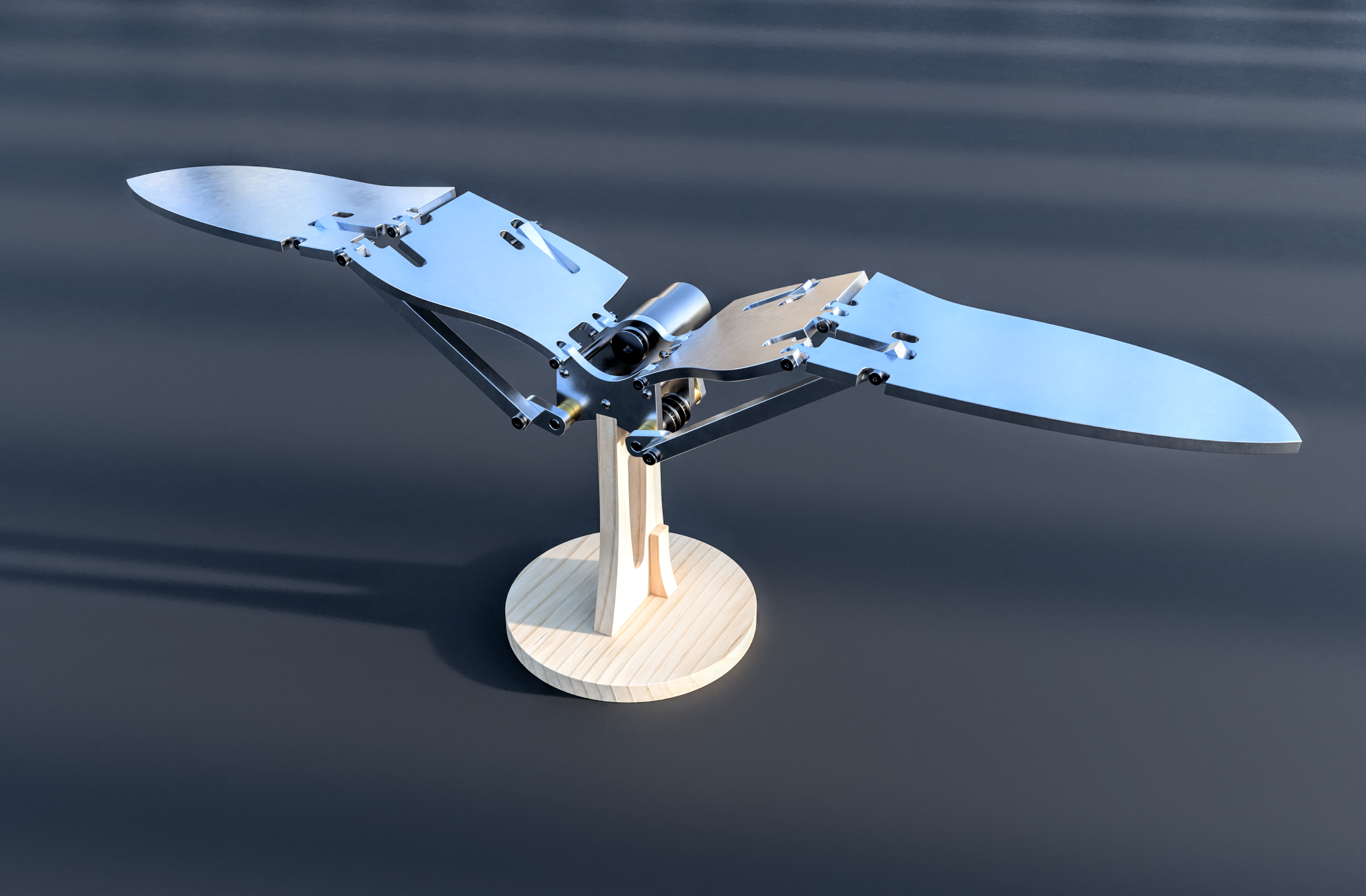
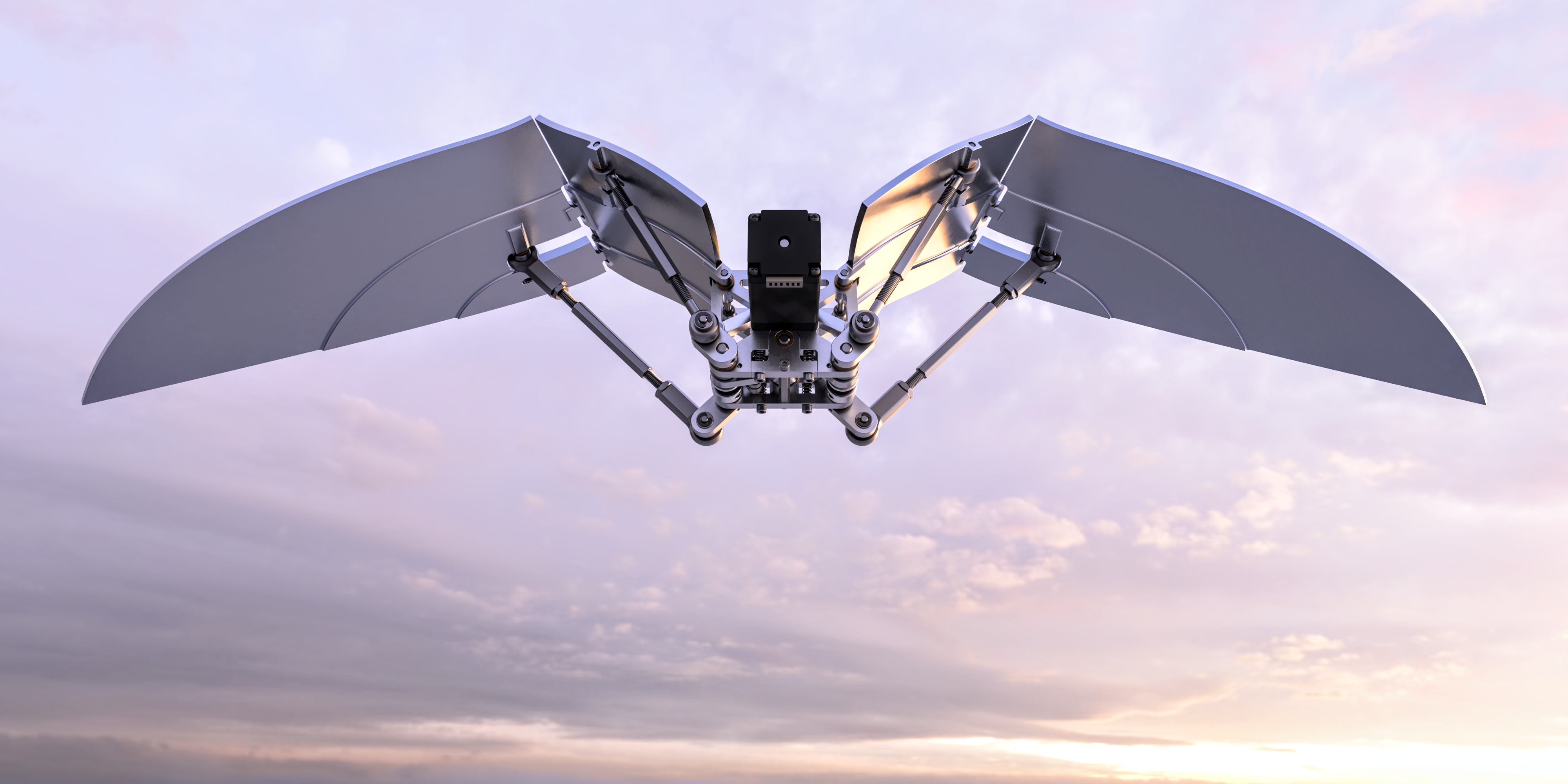
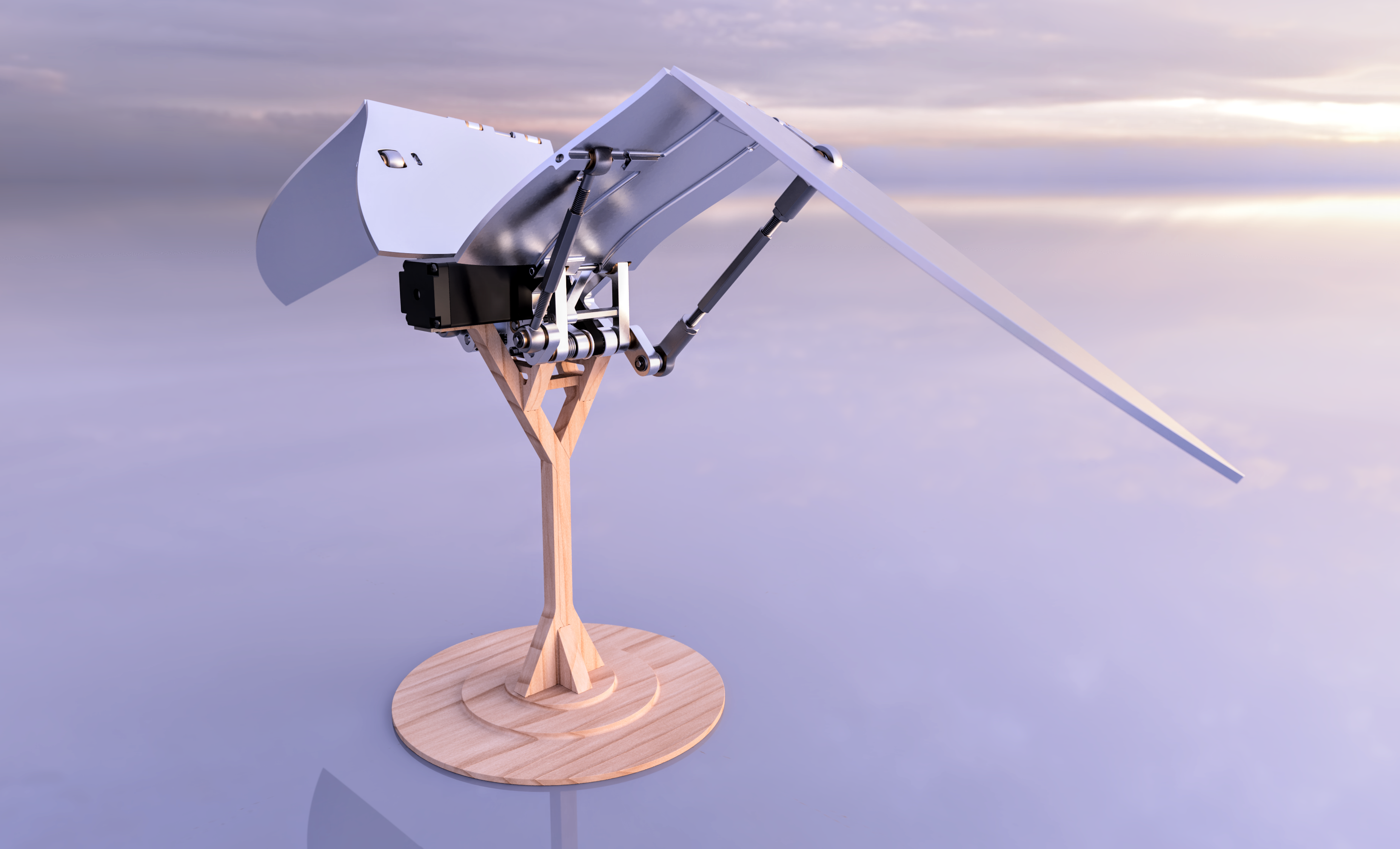
My intention with this project is to mimic the motion of a bird’s wings in flight as faithfully as possible using only rigid components. In its current form it’s probably best described as a desk sculpture for nerds, but I think with some adaptation it could also work well as a mechanical demonstration of sorts for a science center/museum, or as an exploratory STEM kit similar to those from KiwiCo and elsewhere.
(By the way, you can zoom in twice on all the pictures here to see more detail)
Development Process
Original Version
I came up with the original version for a class in college called Component Design. The pandemic was in full force at the time and I happened to be our only fully remote team member, so for practical reasons we divided the project in two — I handled the design while our other members handled fabrication.
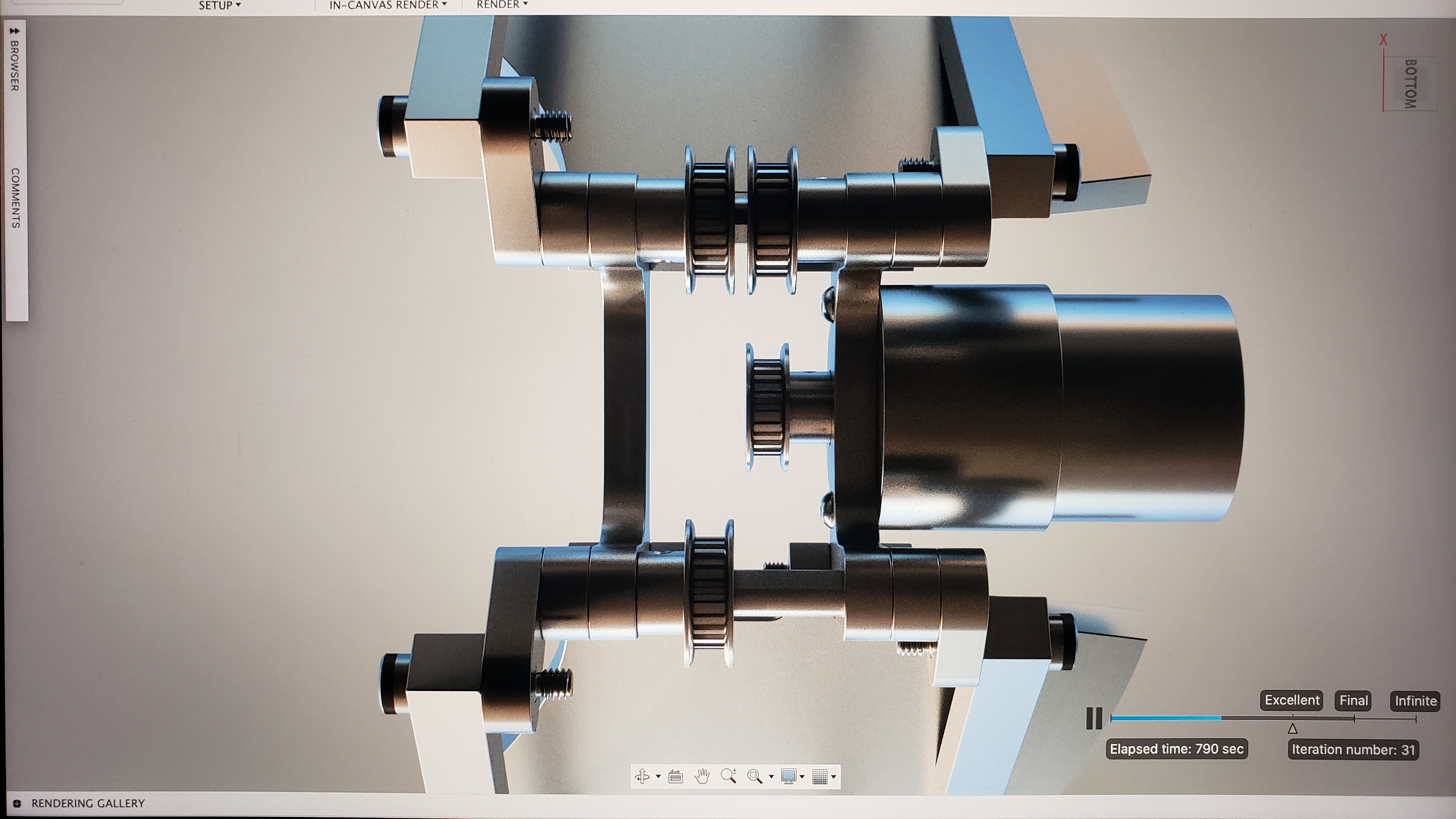
Virtual testbed assembly for component layout and motion refinement
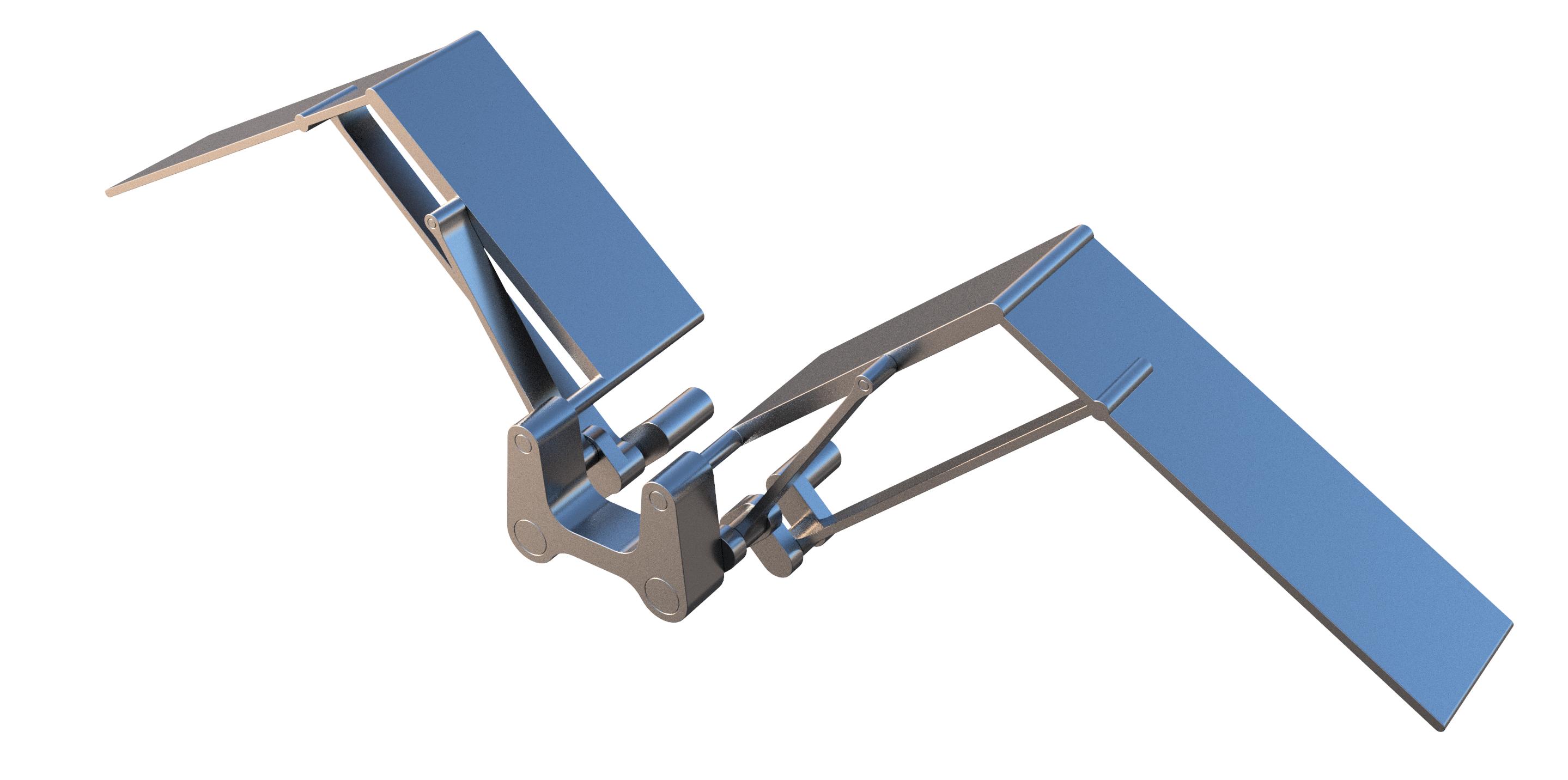

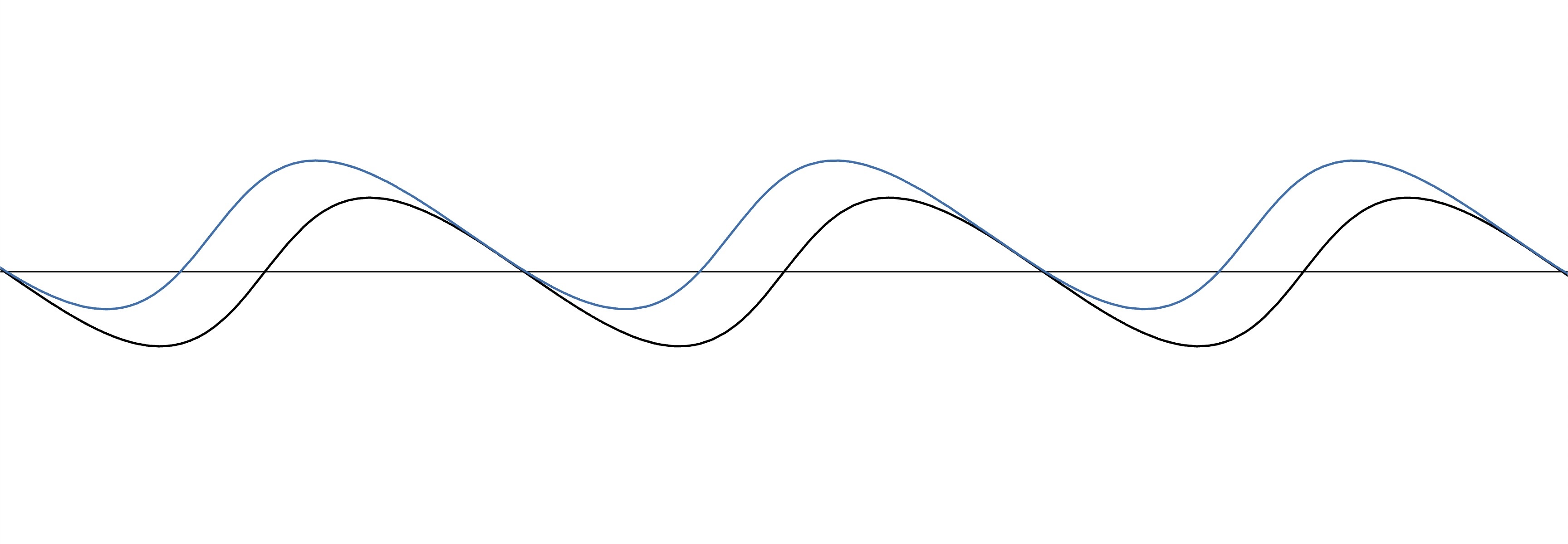
The mechanism is built around two crankshafts, each with two rod journals. The angular offset between the rod journals and their respective crank radii determine the relative motion of the inner and outer wing segments. While it’s a bit of an oversimplification, since the wings rise and fall at different speeds (along with other geometric nuances), the two outputs from the crankshaft can be visualized like so, with the blue function corresponding to the inner wing segment and the red to the outer:
![]()

Further development and incorporation of basic design for manufacturability and assembly

Finished Concept
What also became apparent, after seeing this physical model that the others had built, were the tight tolerance requirements of the struts coupling the crank arms to the wings, especially those connected to the outer wing segments. While I’d gotten an inkling of that from the minuteness of the adjustments I’d had to make earlier while tweaking the motion in CAD, seeing it in real life really hammered home that this would be a problem even with a high-fidelity assembly — more on this later. You can also see they had to improvise a solution for tensioning the belts, an issue I’d completely overlooked.
I was proud of the original design though, even though it wasn’t actually quite finished, so I spent a little more time making a nicer render of it and used it as an opportunity to learn how to make rendered animations:
New Version
A few years later I decided to pick the design back up to finish and improve upon it and fix its numerous issues. My intention behind it is to make the custom components reasonably easy to manufacture from either 1/4” aluminum plate stock using a 2.5 axis CNC router and a drill press, or from any of a variety of plastics using a 3D printer.
Since the wing design was a little rushed the first time, I started with a brief foray into adding feathers, but after disliking both variations I came up with I moved on to the drivetrain.
Since the wing design was a little rushed the first time, I started with a brief foray into adding feathers, but after disliking both variations I came up with I moved on to the drivetrain.


Drivetrain and Central Frame
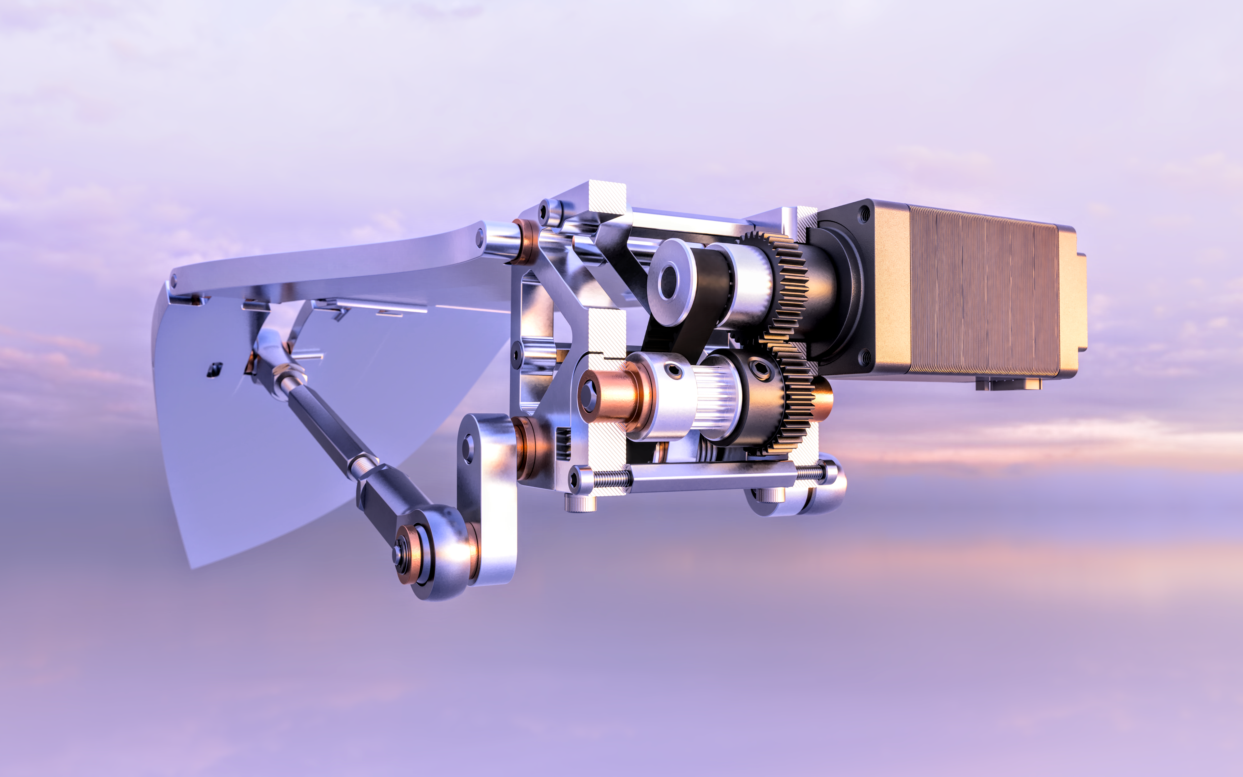
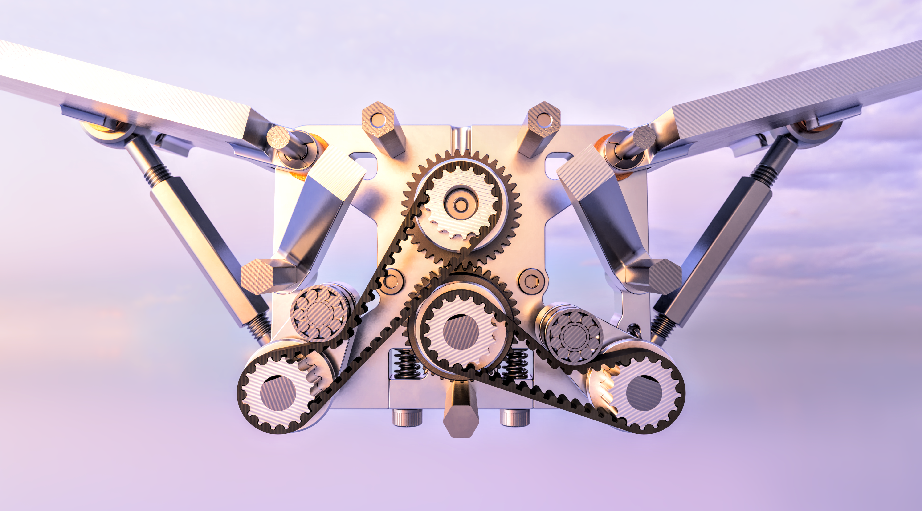
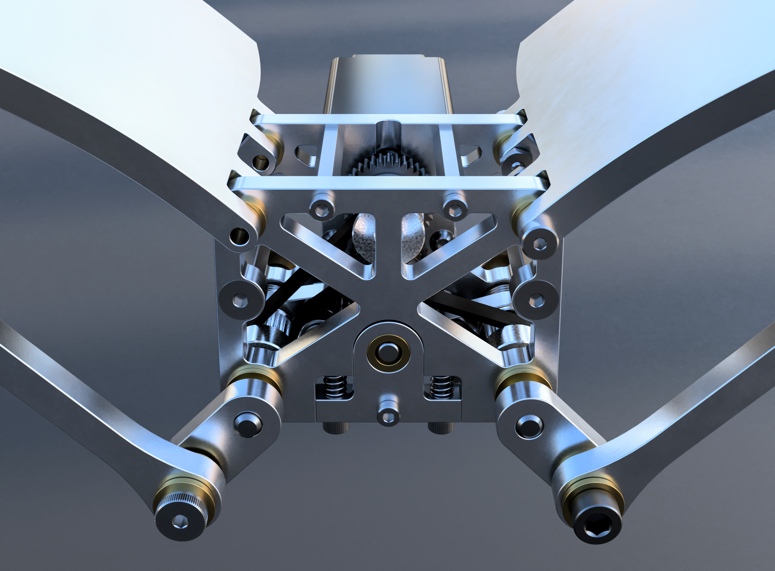
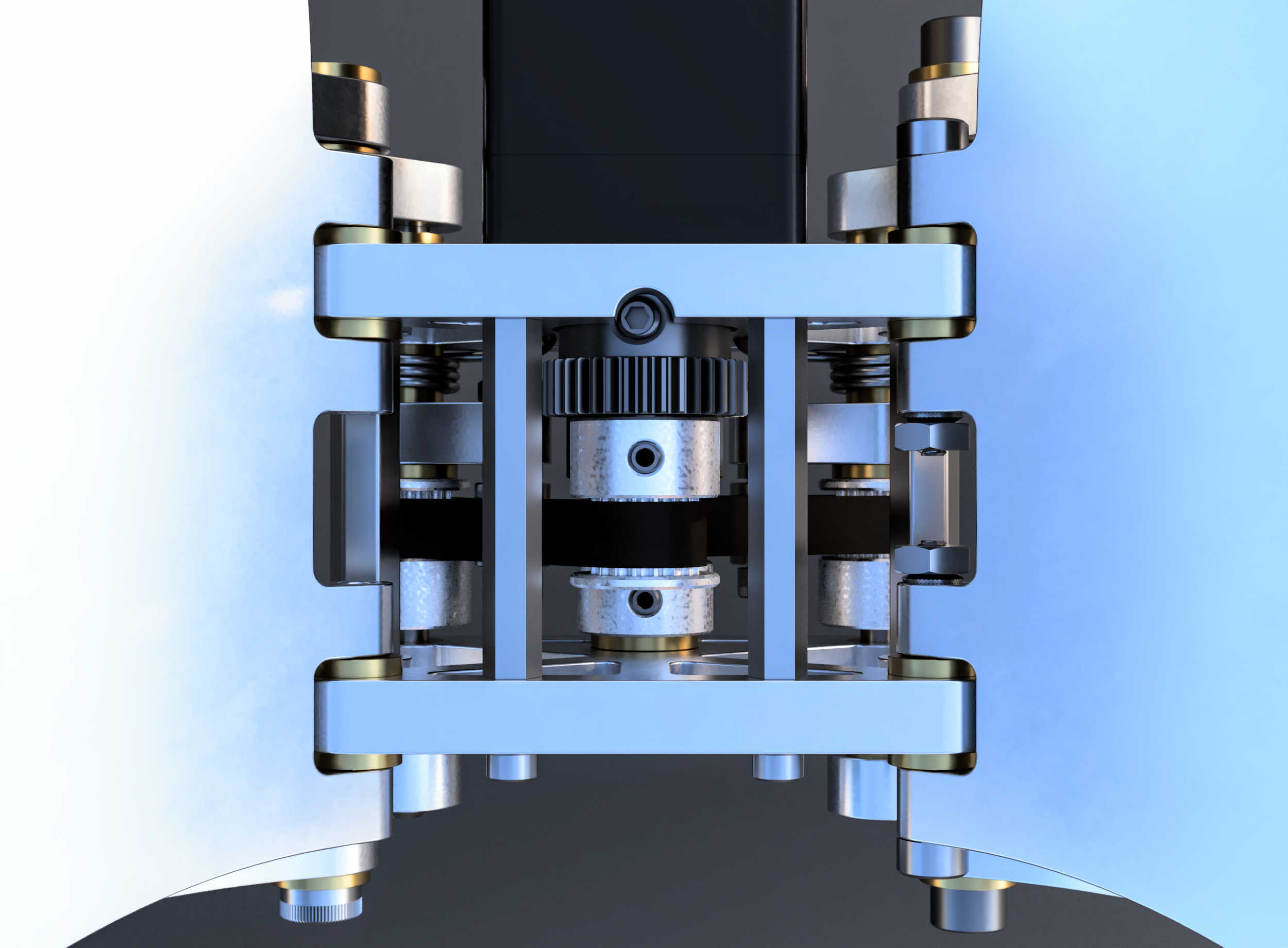
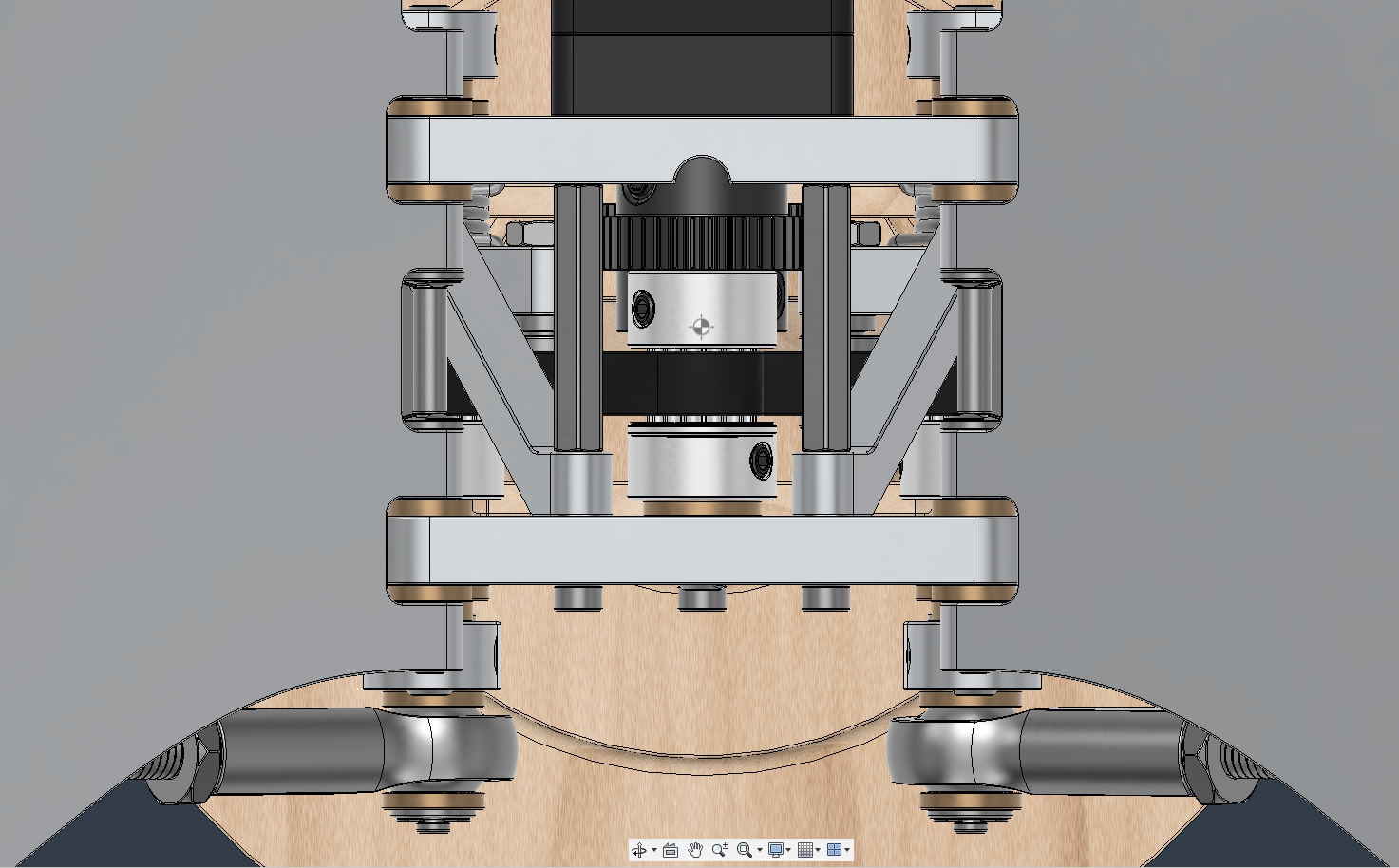
This aspect of the project was never finished the first time, so I started by adding the necessary gears, belts, and pulleys, as well as oil-impregnated sintered bronze bearings on some of the pivot-points (on the 3D printed version these bearings will be made from igus i180 tribo-filament, as will the gears). I also replaced the DC motor with a stepper motor — much better suited to this application since it can be reliably spun at a constant speed while imparting non-constant torque.

I then added more bearings along with spring-loaded belt tensioners and an adjustable gear carriage, which enables fine-tuning gear engagement to minimize backlash. My intention with it is to account for any dimensional inaccuracies (especially in a 3D printed version) and to allow compensation for long-term wear of the gear-teeth, hopefully extending their functional lifespan, though they’ll eventually become worn in ways that can’t be corrected by simply changing their center-distance.

I started cutting out the unnecessary parts of the frame so that the mechanism is visible, and made the design of the strut arms a little nicer, though I ended up replacing them almost immediately
That semicircular groove in the rear frame piece allows the driving gear’s set screw to be tightened
Wings
Like I mentioned before, the strut arms were a little tricky — it was essentially a consequence of how close the struts and outer wing segments got to being coplanar, which meant that, while accounting for the tolerance stackup between all the components in the wing-chain, the strut length also needed to be within a very tight range for the wings to move right. Manufacturing all the custom components in that chain to the necessary tolerances, equal to a small fraction of the coupling strut’s allowable range, would increase their cost in some cases by multiple orders of magnitude, not to mention all the off-the-shelf components, few to none of which are manufactured with that kind of precision.
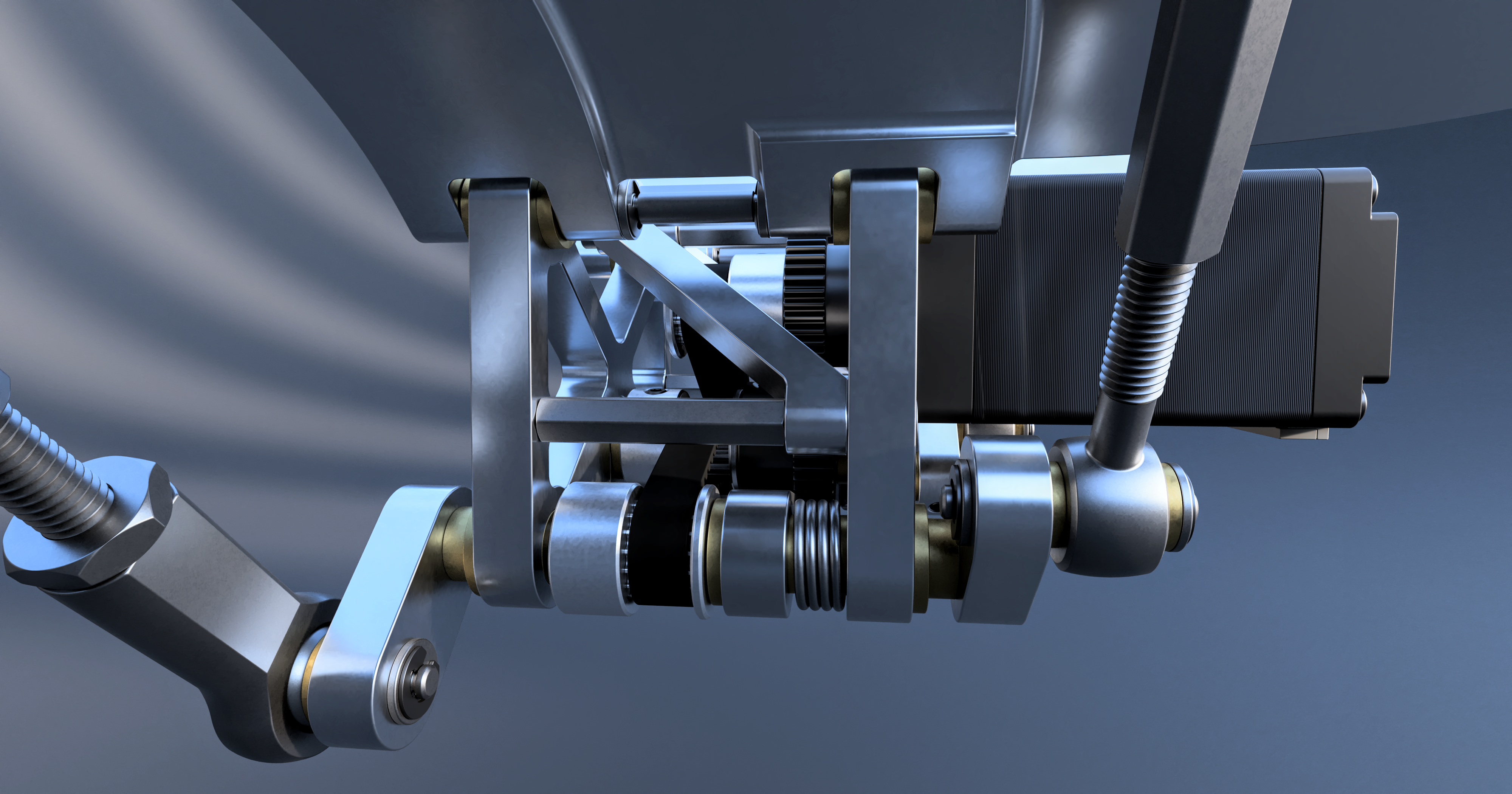
The only practical solution I saw was to make the struts adjustable, for which I used two different strategies. For the rear struts driving the inner wings I used a standard right-hand thread on both ends, which lets them be adjusted down to 1/64th of an inch, though they have to be disconnected on one end to do so. On the forward struts/outer wings I used a turnbuckle-style setup, composed of a right-hand thread on one end and a left hand on the other, which allow the struts to be adjusted to any length in their range without being removed. I chose the discreet, quantized adjustment strategy for the inner wings since they’re less sensitive, have fewer tolerances to stack up, and a small asymmetry between wings is much more noticeable in the angle between wing segments when they’re fully outstretched than at any point between the wings and frame. It is possible I’ll redesign the inner struts with turnbuckles after finishing the first prototype if the alignment isn’t good enough, but turnbuckles are expensive, so I really hope I can avoid that.
This adjustability also means that if someone wanted to change the motion of the wings a bit to suit their liking, they absolutely could.
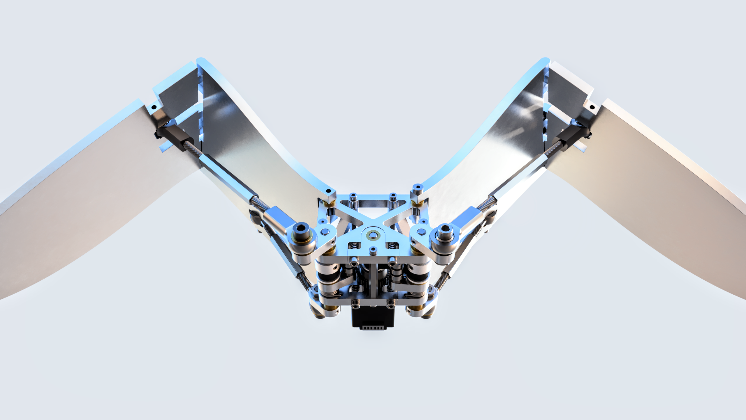
As you can see above, I also decided to mount the outer wing segments at a 16° angle so that they bend out of plane, meaning the wings to fold backwards as well as downwards on the upswing — like a real bird. It also requires the coupling struts for the outer wings to be mounted on ball joints, which was what originally intimidated me about this design element, but in the end it wasn’t that difficult to implement.
Another detail that might not be immediately obvious is that half the shoulder bolts I’m using above to fasten the coupling struts to the crankshaft need to have left-handed threads to avoid being loosened over time. I really struggled to find a source for left-hand-threaded shoulder bolts of the right size though, especially ones that weren’t insanely expensive, so I pivoted to using plain shafts with retaining ring grooves instead, which also give me more flexibility with other aspects of the assembly. The retaining rings themselves are cheap and easy to find, but I’ll have to cut the shafts to length and add the grooves for the retaining rings myself. My plan is to design a small 3D-printable jig to accomplish that using a dremel instead of a lathe, since I don’t have one, but a lathe would of course be better.
Another detail that might not be immediately obvious is that half the shoulder bolts I’m using above to fasten the coupling struts to the crankshaft need to have left-handed threads to avoid being loosened over time. I really struggled to find a source for left-hand-threaded shoulder bolts of the right size though, especially ones that weren’t insanely expensive, so I pivoted to using plain shafts with retaining ring grooves instead, which also give me more flexibility with other aspects of the assembly. The retaining rings themselves are cheap and easy to find, but I’ll have to cut the shafts to length and add the grooves for the retaining rings myself. My plan is to design a small 3D-printable jig to accomplish that using a dremel instead of a lathe, since I don’t have one, but a lathe would of course be better.
Especially after rotating the mid-wing joint, I felt that the wings needed a complete overhaul.
An early version exploring chamfer-style wing steps
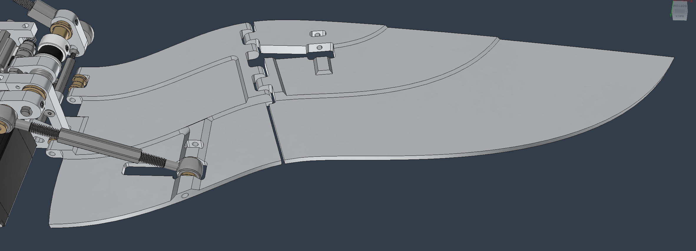
A couple rough bits left

Done, for now
Stand
Version One
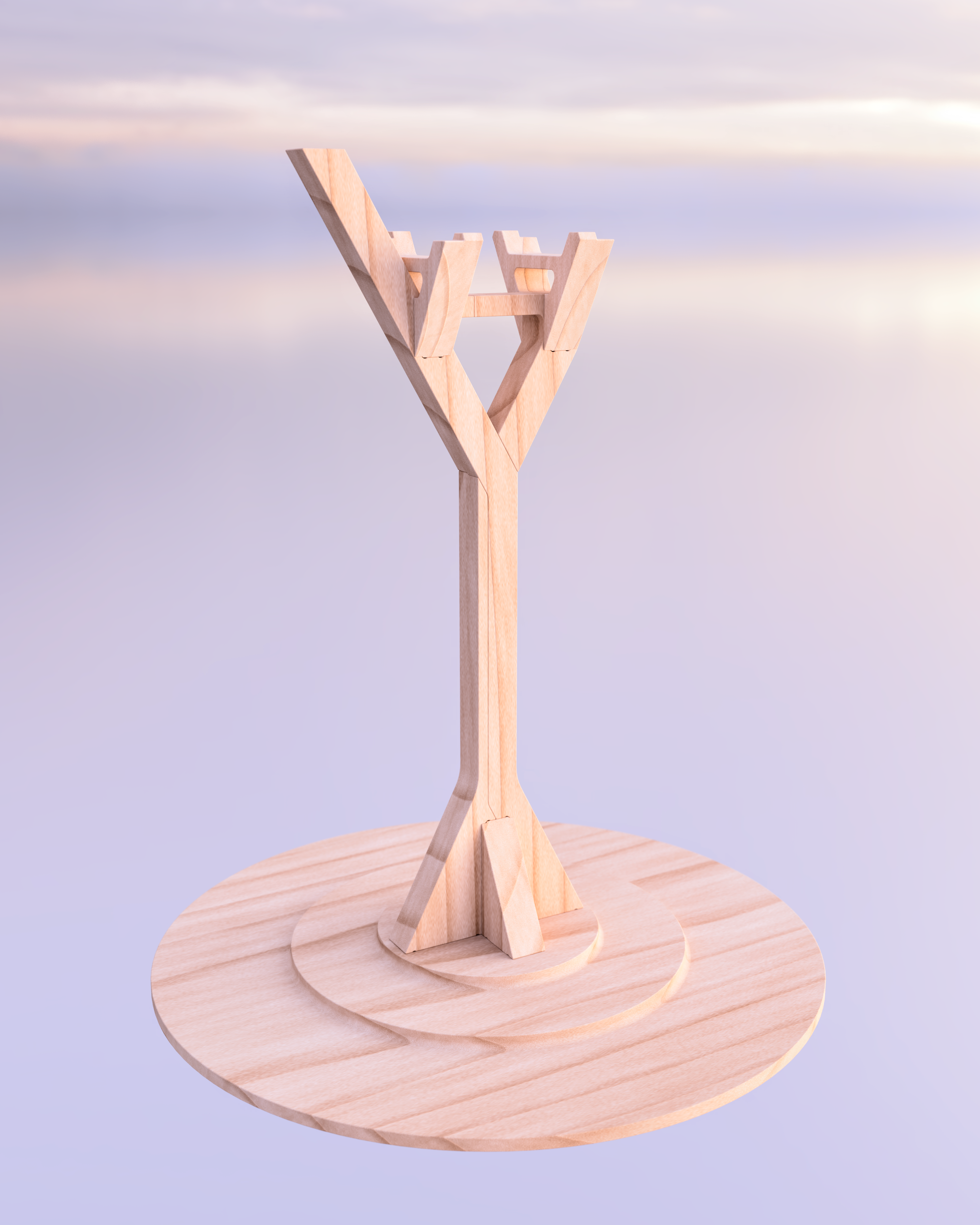
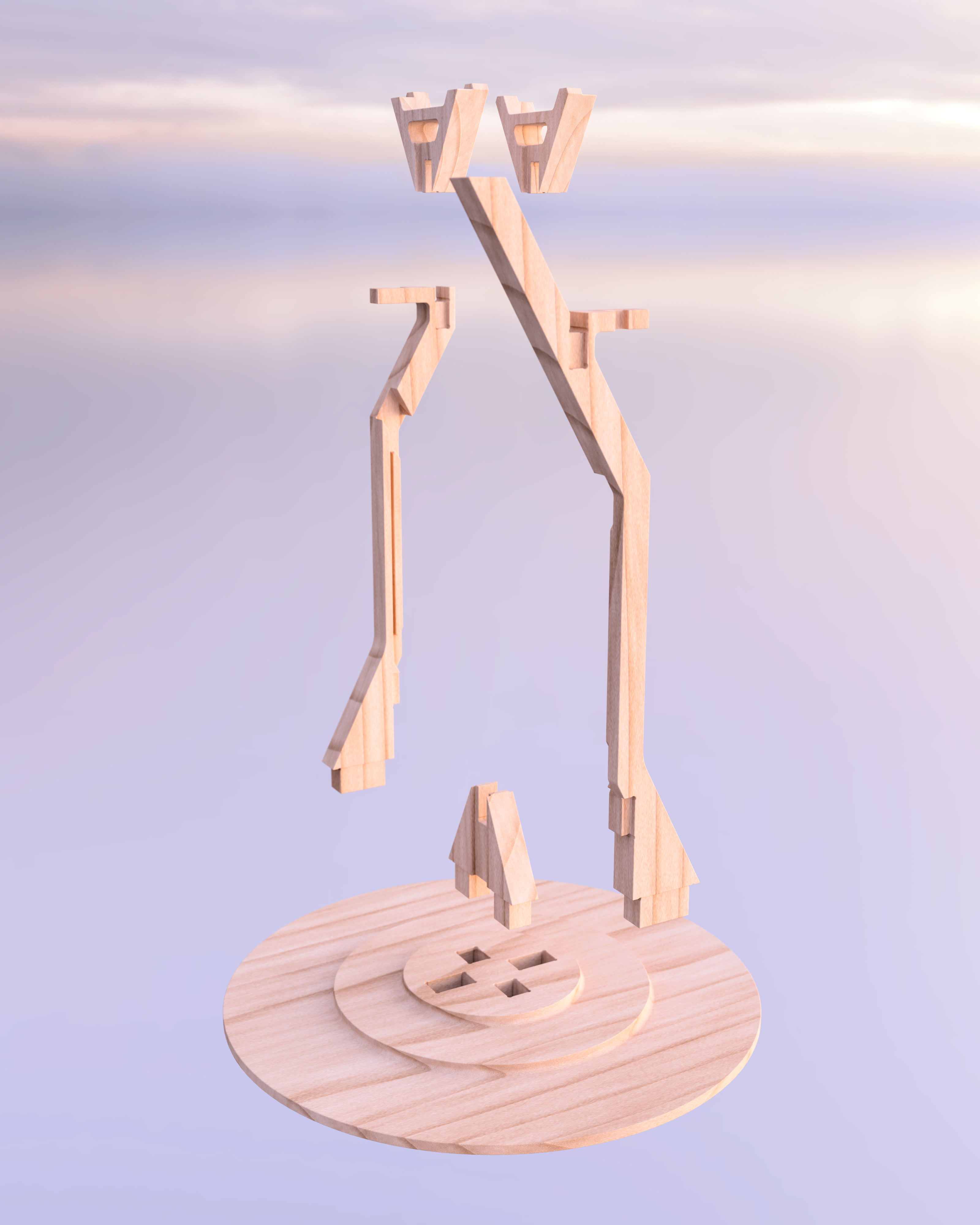
For this part of the project I was heavily inspired by traditional Japanese carpentry, which is notable for utilizing complex interlocking joints carved directly into the wooden components to secure them together, rather than the fasteners used in most western cultures; you can see lots of great examples here. I did make some modifications to the formula though to accommodate CNC manufacturing and to allow the stand’s ‘branches’ to taper more seamlessly as they extend upwards, and while I did my best to avoid using any fasteners, I did end up securing the electronics inside with a few screws.
In this first version, the long vertical trunk-like pieces sort of twist together to form a more secure connection (the two halves of the bridging-strut portion near the top fit into each other from the opposite side).
In this first version, the long vertical trunk-like pieces sort of twist together to form a more secure connection (the two halves of the bridging-strut portion near the top fit into each other from the opposite side).
Version Two
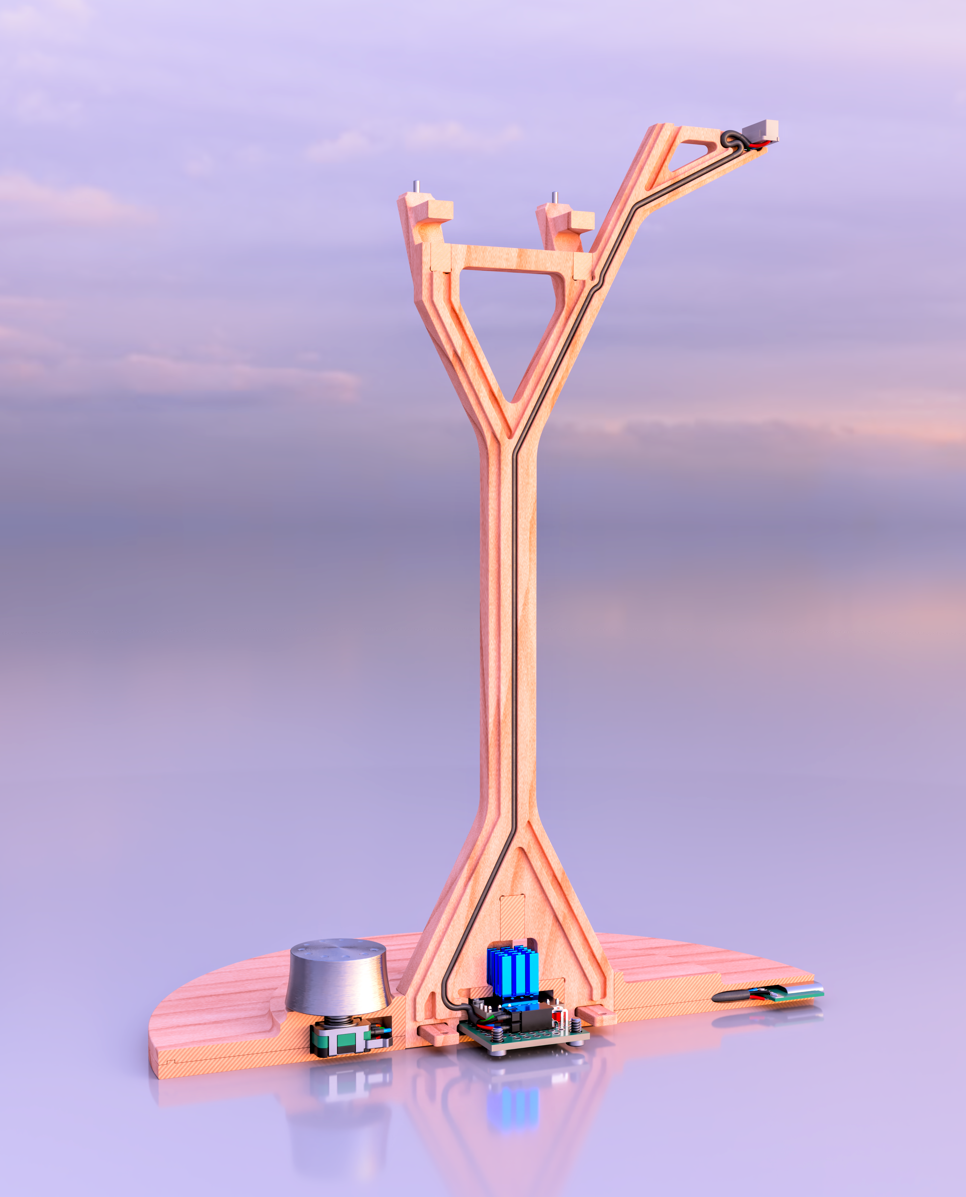
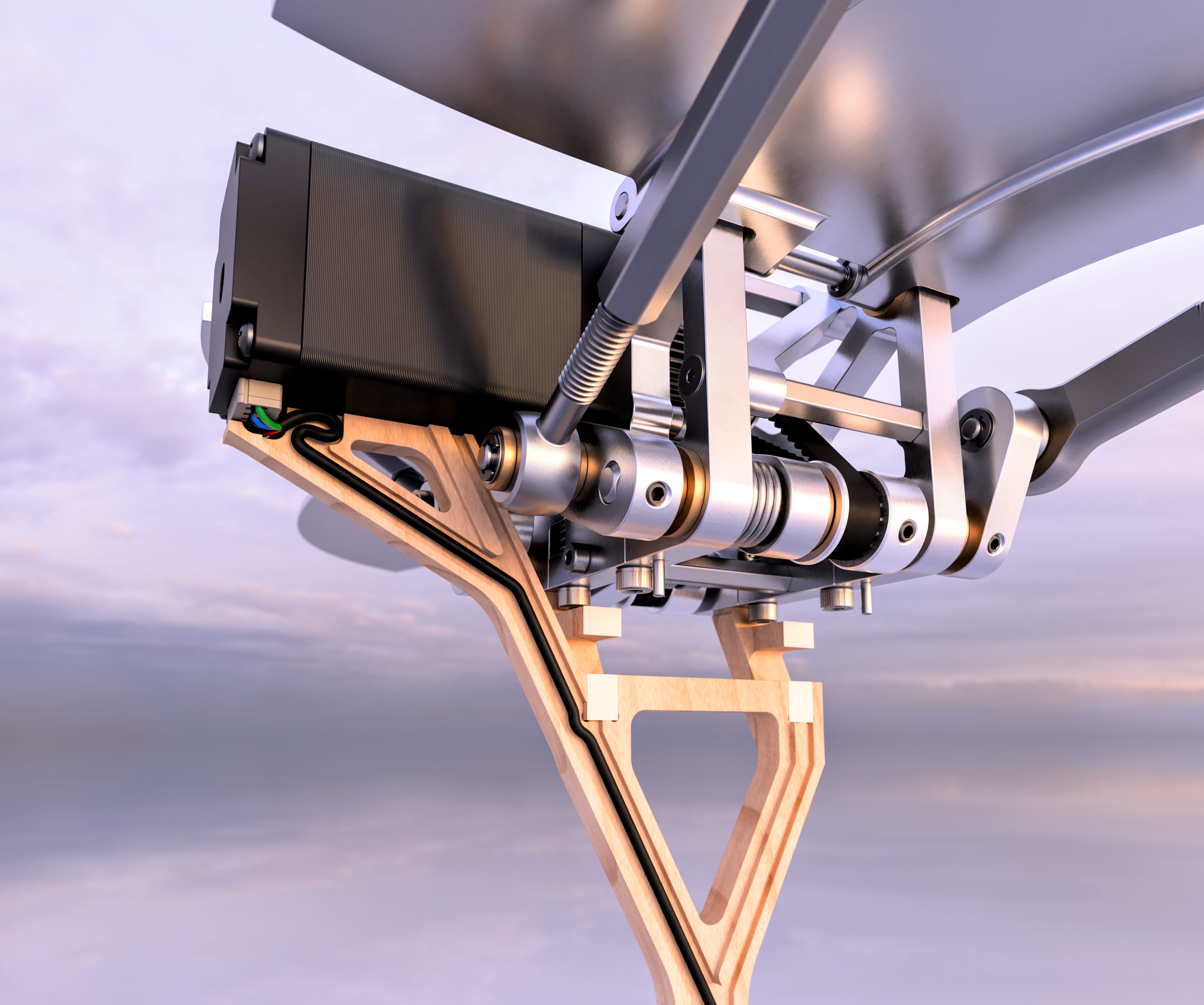
After designing all the above I realized I needed an actual way to run a hidden wire up through the stand to the motor, which would require a third piece if I used the entangled design, so I decided to pivot to a simpler clamshell strategy. The rails and depressions are there to create both a robust connection between the two halves and a shadow line, which makes the seam prettier by preventing any light from shining through.
I wanted the bird mechanism to be easily removable, so it’s secured on top of the stand with four pins which fit into holes in the bottom of the two main halves of the central frame.
I wanted the bird mechanism to be easily removable, so it’s secured on top of the stand with four pins which fit into holes in the bottom of the two main halves of the central frame.
I also intend to design another style of mount that will allow the whole mechanism to be hung from the ceiling, but I haven’t explored that idea in detail as of yet.
Electronics
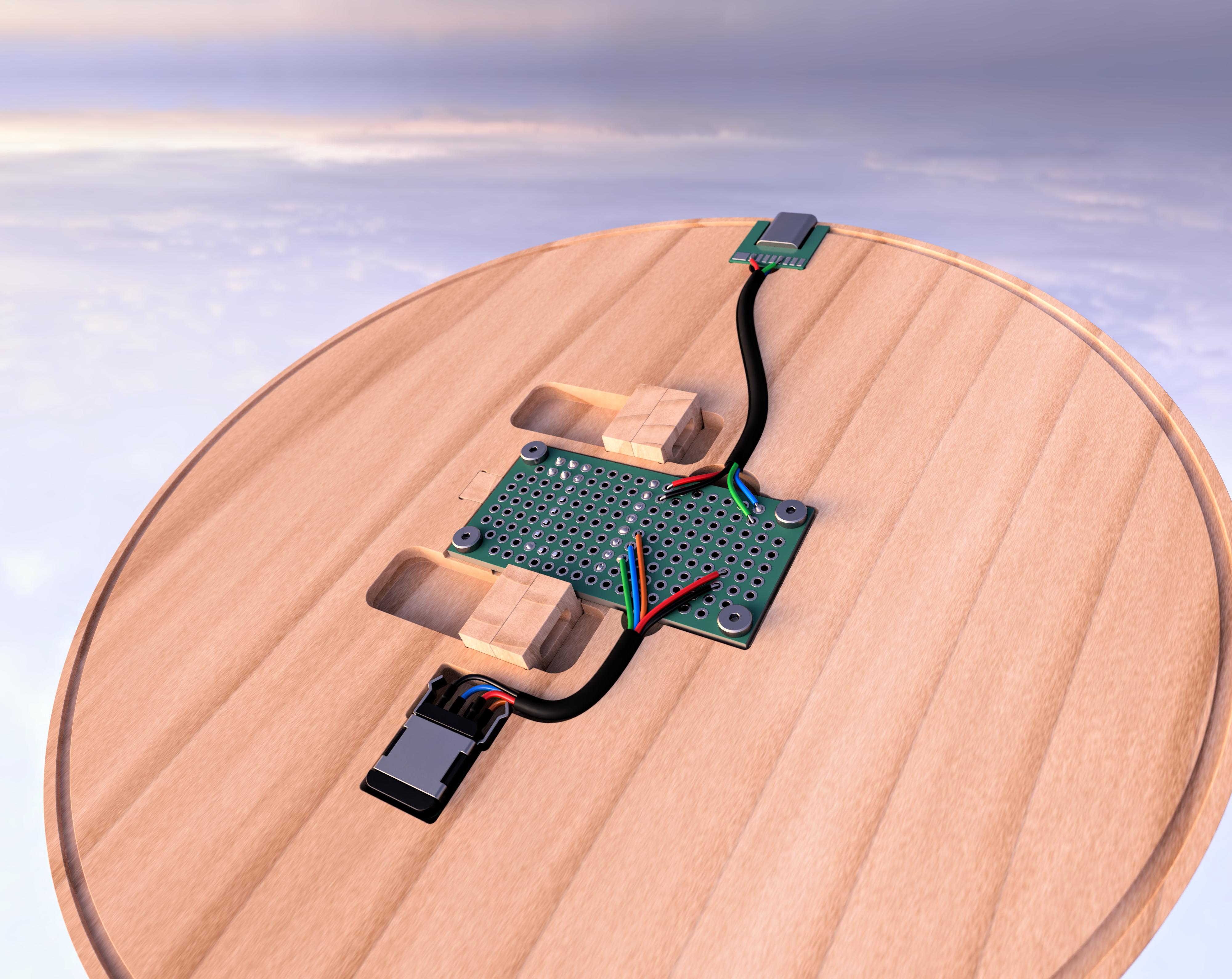
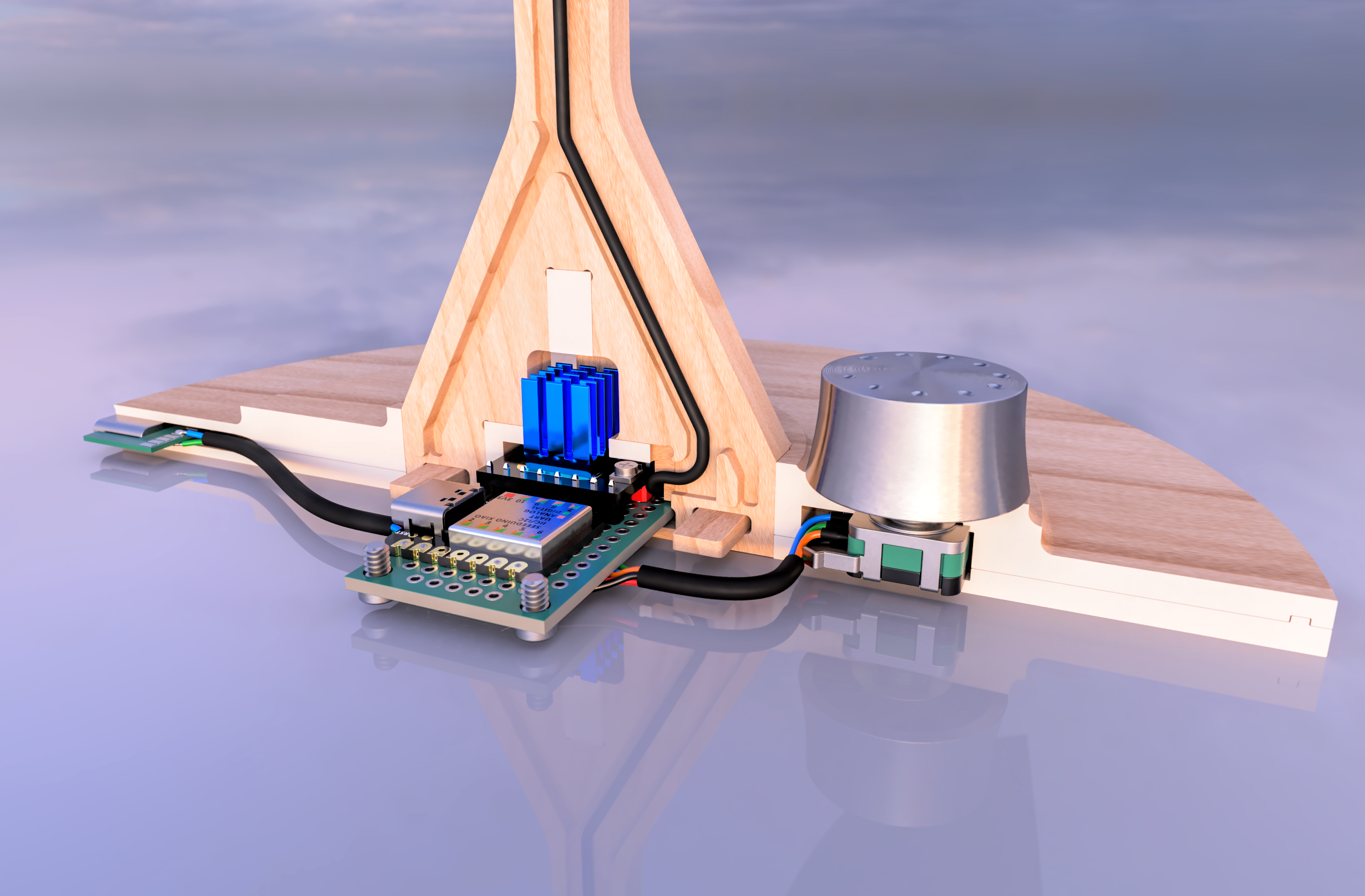
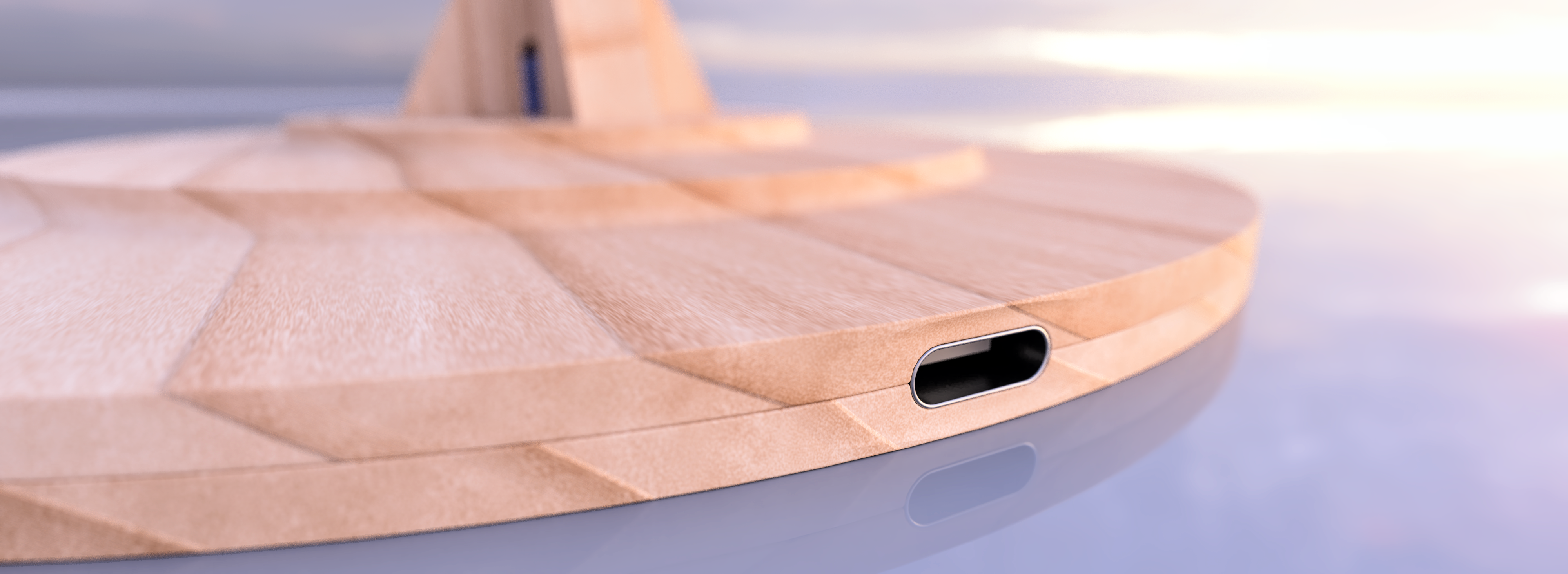
The electronics fit inside the thickest part of the base of the stand, with the heatsink on the stepper motor driver extending up into the bottom of the ‘trunk’. The driver I’ve chosen is the TMC2209, which produces much less heat compared to similar drivers, but it does still produce some, so I’ve included four vent holes in the base of the stand around the heatsink to allow that heat to dissipate. Another cool thing about that driver is that it supports up to 256 microsteps, which lets the stepper motor run nearly silently without requiring any mechanical changes. I’ve included an allowance for a kink in the wire connected to the motor, which will allow the mechanism to be attached and removed from the stand more easily.
Most of the mechanical off-the-shelf components I’ve included had models available from McMaster, so all I had to do to them was add PBR materials and cosmetic fillets, but most of the electrical components either had no models at all, or had very low-quality ones, so they required a lot more work. I only added fillets to the Seeduino microcontroller on the right below, and other than remaking the heatsink and doing a ton of cleanup on the stepper motor driver on the left I mostly left it alone, but I made all the other parts from scratch.

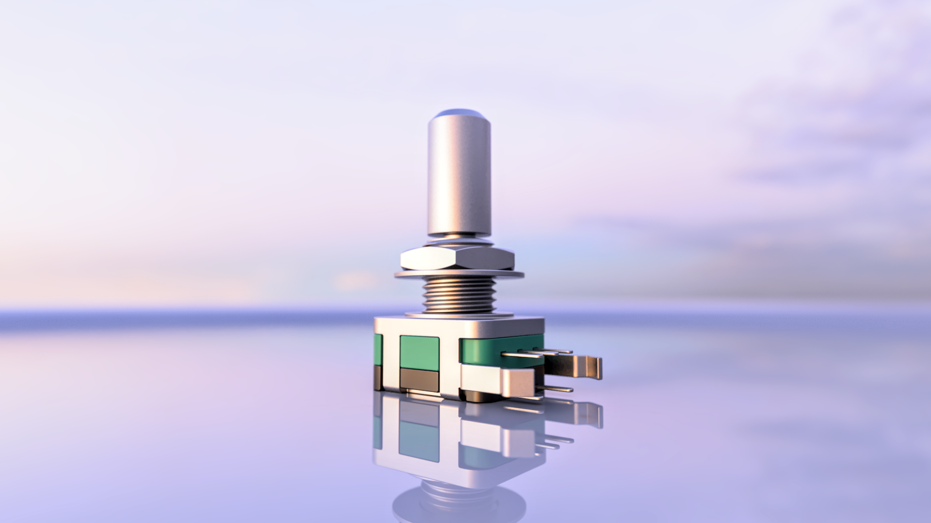 This potentiometer has a momentary button built in, which I intend to use to toggle the motion on and off. It had a datasheet with fully dimensioned drawings, which was very appreciated.
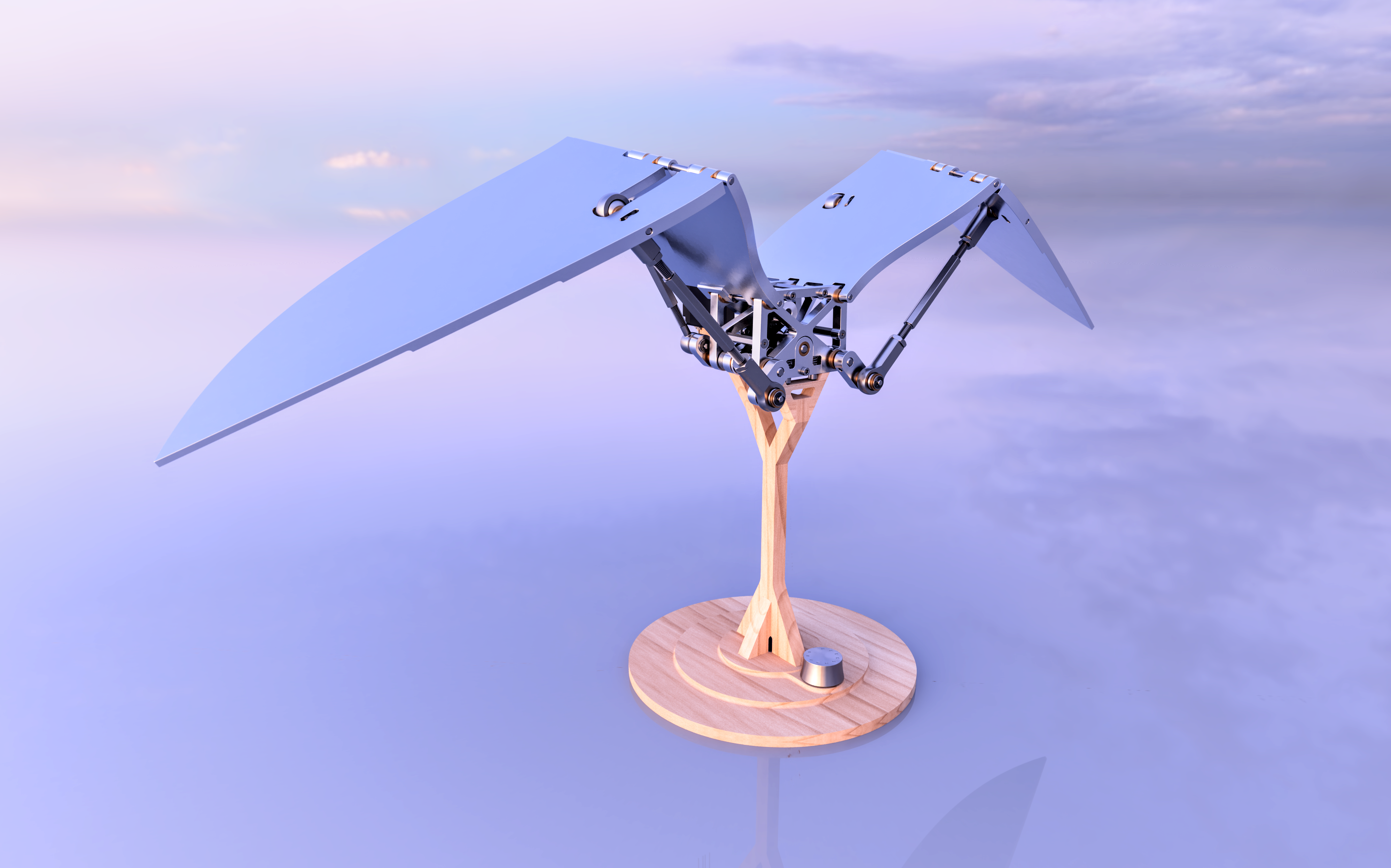
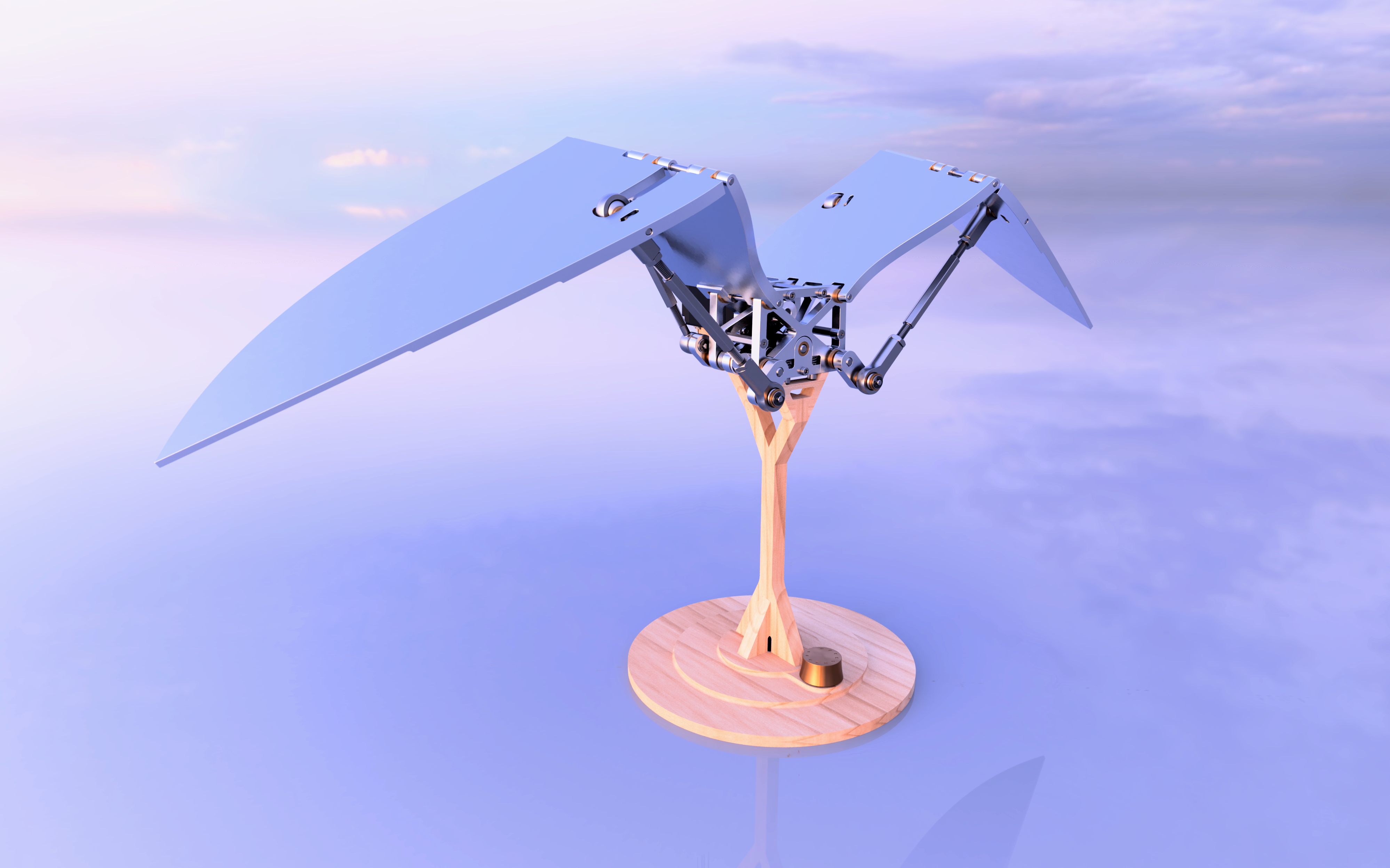
 This knob model was based on pictures and a couple measurements of this custom guitar knob. It’s attached to the potentiometer and will adjust the speed of the wings.
I tried both bronze and steel versions of the speed knob, I definitely prefer steel. You can also see the vent holes for the heatsink at the base of the trunk here.
Center of Mass and its Variance
The Center of Mass varies as the assembly moves of course, but not just vertically — since the outer wings rotate out of plane it also varies horizontally front-to-back, so it’s especially important to ensure that the mechanism has a stable perch on its stand. You can see the two mass-center-extremes below; The CoM of the entire mechanism is on average just a bit behind the center of the circular foot of the stand, which I think is pretty much perfect, since the ‘branches’ are set up with more support at the back and, if it were ever to be knocked over, it would be a bit more likely to fall rearward, rather than forward and potentially out or off of wherever it’s placed.
Rendering
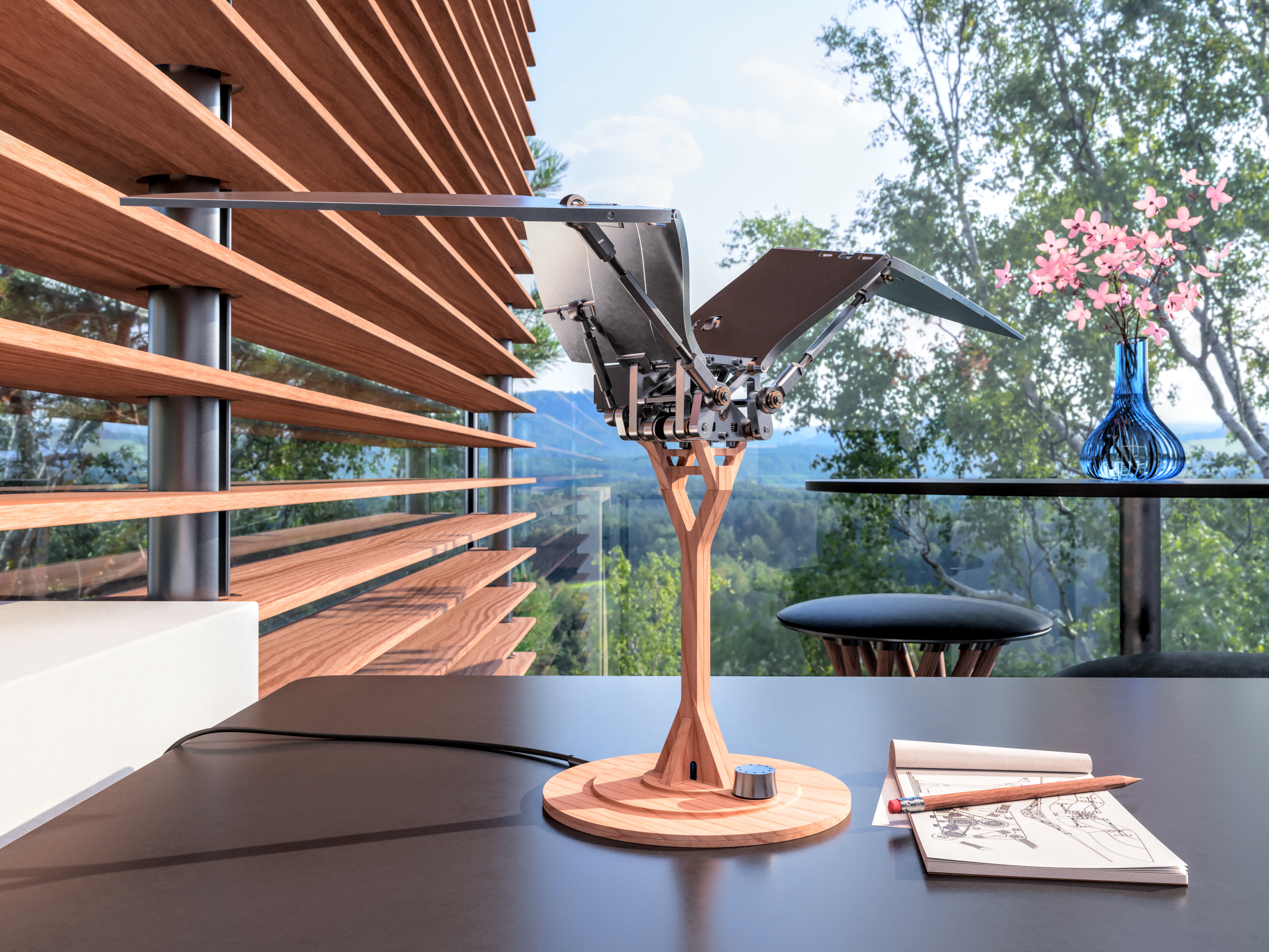
I modeled nearly every part of the scene, including objectively superfluous things like the pencil and sketchbook — though these do help to convey scale. The only things I didn’t model were the flowers, which I grabbed out of a CC0 vase model and rearranged to fit in my own vase design (which is a previous project of mine, along with the stool). I also didn’t create the HDRI background, and I constructed the PBR materials using premade texture maps, though they are all of course CC0 as well. I definitely spent too much time iterating on this render, but the same could be said about the rest of the project, so at least I’m consistent — you can see many of my iterations below:
Last Minute Motion Refinement
After spending all that time polishing the renders, I had a sort of dumb epiphany and realized that, to solve a lot of the motion issues I’d failed to completely eliminate earlier, I could simply turn the crankshafts in the opposite direction (after adapting the angular offset between the crank arms for it of course). This, like almost everything, ended up being less simple than anticipated and required several changes to the wings’ proportions, as well as to the position of the belt tensioners, but in the end it did solve a lot of my frustrations with the motion.
Like I mentioned before, the crankshaft output can be represented, approximately and qualitatively, by the graph below, but when combined with the wing geometry things get a little more complicated.
The moment arm by which the wing segments are driven effectively varies in length depending on the position of the crankshaft; when the crank pins are on the underside of the crankshaft, the moment arm is large, causing the wings to move slowly relative to the crankshafts’ rotation. Conversely, when the crank pins are facing upward, toward the wings’ pivot points, the moment arms driving the wings become small, in some cases smaller than that of the crankshaft itself, momentarily mimicking an overdrive gear ratio and resulting in an inaccurate and undesirable downward snapping-motion of the wings. For a desk toy this could actually be a safety issue, not to mention causing unnecessary stress on the motor and other components. I’ve constructed the 4-bar linkage below using this framework to demonstrate an exaggerated version of the effect. While the inner wing linkage is a 4-bar, the outer wing linkage is not, so this is again only an approximation.

Below is some fantastic footage I used extensively as reference for how real birds fly. This one is good too. As you can see, the upstroke is faster than the down, somewhat akin to swimming through the air, which is the opposite of my original mechanism; this was my main motivation for reversing the crankshaft rotation.
Before
After
You can also increase the playback speed of the videos above to see the effect more clearly.
I had to make some changes to the wings’ proportions, especially the inner segments, and reposition the belt tensioners to the newly undriven, slack sides of the timing belts.
I had to make some changes to the wings’ proportions, especially the inner segments, and reposition the belt tensioners to the newly undriven, slack sides of the timing belts.


The same condition that caused the downward snapping motion also made the mechanism extremely sensitive to proportional changes. Consequently, the point in the assembly’s motion below, when the wings are fully outstretched, required unreasonably tight tolerances of the outer coupling struts; even an obnoxiously small difference in their length, or of the dimensions of any one of the components in the wings, frame, and crankshaft, would cause the wings to be noticeably assymetric.
And this is how things look after the mechanical redesign. The near-coplanar condition affecting the outer wing segments is essentially eliminated since the wings are now bent when the crankshaft pins are facing toward them. I decided to keep the adjustable coupling struts for customization, but they are far less mechanically crucial than they were before.
There are still aspects of the motion that bother me a little, but I’m letting it rest for now until I finish building a real prototype, since that will let me iterate much more quickly and help to uncover all the real-world problems I’m not properly anticipating. As an example of that, the crankshafts don’t have any counterweights, and while their lateral vibrations will cancel each other out overall, that isn’t true of their vertical vibrations — I don’t think that will be a problem in the speed range I’m planning to allow, but I’d be lying if I said I was sure.
Here’s a compilation of some of my iterations on the motion:
While doing research later on in the project I also fell down the rabbit hole of ornithopters and the various mechanisms they employ, which has inspired me to attempt to build a flightworthy ornithopter at some point, since this project is most certainly not that. It would be fun to see if a similar mechanism could successfully drive the wings of an ornithopter though, after drastic weight reduction of course, or if the more common mechanism, which you can see examples of here, here, and here, is really just much better suited to this application (it likely is). The alternative, unarticulated wing strategy that relies on flexible membranes can also be very cool and would definitely be a simpler place to start, but I’ll cross that bridge when I get to it.


Physical Prototype
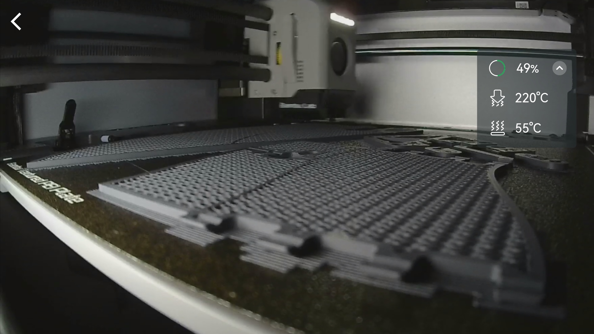
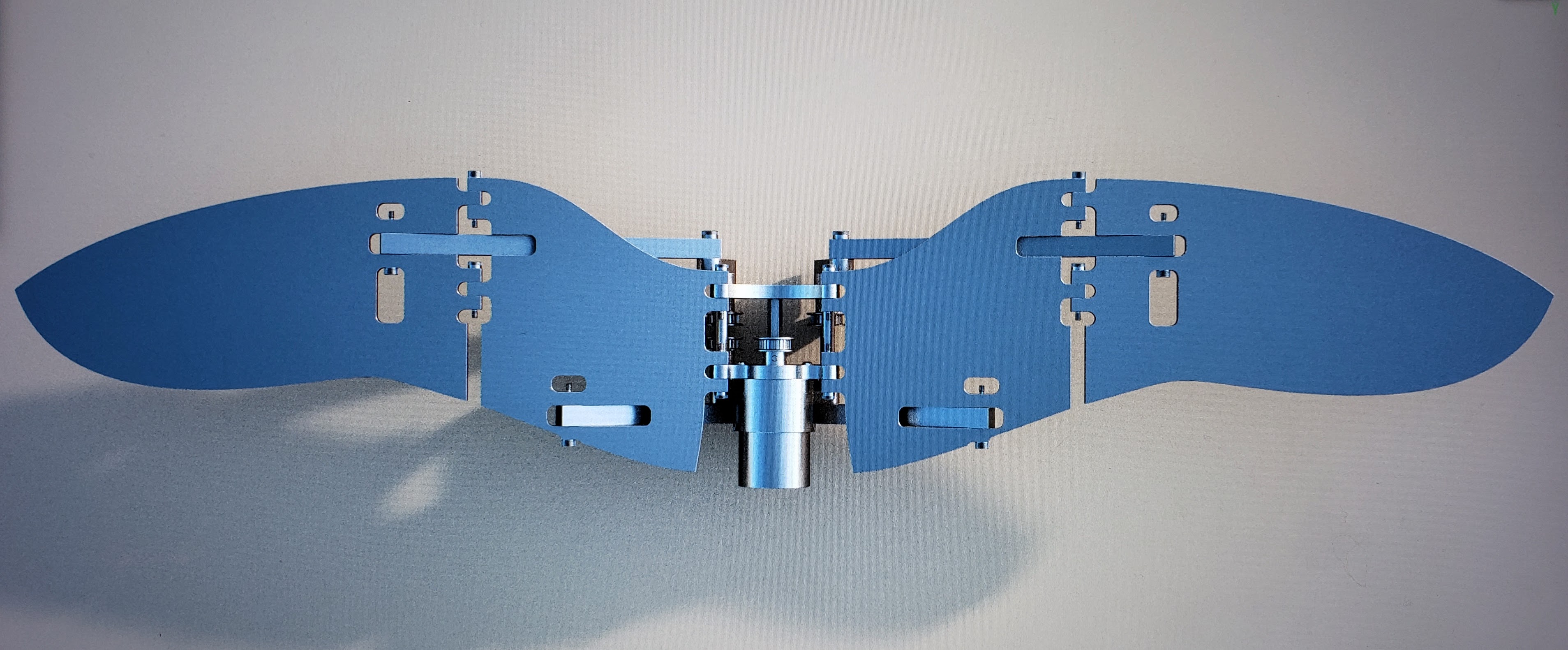
I’m currently in the initial stages of building a physical prototype of the design. For speed and economy reasons I’m 3D printing the custom components, many of which you can see below, as well as some of the off-the-shelf ones. I’ve been a little preoccupied with other parts of my life lately, but I’ll add a larger section about it here when I’ve made more progress.

Thanks for looking!
